


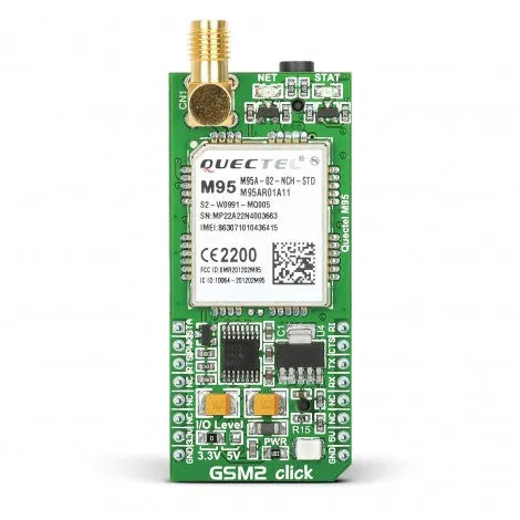
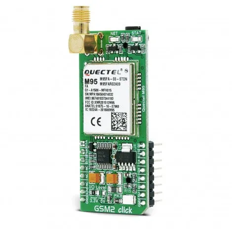
GSM2 click is a compact quad-band GSM cellular network communication solution, featuring the GSM/GPRS Quectel M95. This module features a full set of options for the cellular networking and communication, such as the network status indication, jamming detection, embedded internet protocols, including TCP/IP, UDP, FTP, PPP, HTTP, SMTP, full GPRS multislot class 12 implementation, it is fully compliant to GSM Phase 2/2 , and more. Data communication speed is rated up to 85.6 kbps for both uplink and downlink connection. This module offers high quality integrated audio interface, allowing voice communication over the onboard 3.5mm headset connector.
GSM2 click supports quad-band GSM/GPRS, allowing it to be used worldwide. A wide range of communication protocols and connectivity options, packed in the compact size module, driven by the simple AT command interface via the UART bus, make this click board™ a complete solution for a wide range of M2M applications, such as mobile Internet terminals, automatic meter reading (AMR), remote monitoring automation and control (RMAC), surveillance and security, road pricing, asset tracking, wireless points of service (POS) and similar applications, which rely on a cellular network connection.
How does it work?
GSM2 click is equipped with the , a compact, quad-band GSM/GPRS module, from Quectel. It covers frequencies of 850/900 MHz with up to 2W, and frequencies of 1800/1900 MHz with up to 1W transmitting power. The M95 module is also compliant with the eCall EU Directive. This module is the main component of the click board and it consists of a number of internal blocks or sections, such as antenna switching section, RF transceiver section, memory, power management, and most importantly - the cellular baseband processor. The module interface consists of several lines used to report the device and the network status, SIM card interface lines, UART interface lines, and device control lines. These lines are routed to the respective elements of the Click board™.
The M95 module has to be powered by a clean and stable power supply. The voltage needed for the module to work properly is about 4V and it is derived from the 5V mikroBUS™ rail, through the MCP1826, a 1A low drop output (LDO) regulator from Microchip. Although the M95 is a low power device, the cellular network modules in general, are notorious for their high power consumption, so the 1A LDO had to be used.
Digital sections of the M95 are internally supplied by 2.8V, so it is necessary to condition the communication bus lines which connect the host MCU with the module. M95 outputs 2.8V output from its internal LDO, providing a needed reference voltage for one side of the TXB0106, a 6bit bidirectional level shifting and voltage translator with automatic direction sensing, from Texas Instruments. The reference voltage for the other side of the level shifter is taken from the onboard SMD jumper, labeled as I/O Level This jumper is used to select between 3.3V and 5V from the mikroBUS™, depending on the used MCU type and its logic voltage level requirements.
UART interface supports baud rates from 300 bps to 115.2 kbps and automatic baud rate detection for up to 115.2 kbps. The automatic baud rate detection mode is set by default. The UART bus of the M95 module is connected to one side of the level shifter, while the other side (shifted) is connected to the respective mikroBUS™ UART pins (TX and RX). However, the M95 module is designed as the traditional DCE device (Data Communication Equipment) offering the full UART pin count, including the hardware flow control pins (CTS, RTS). These pins are routed to the mikroBUS™ CS (RTS) and the INT pin (CTS) and can be used in the MCU software if the hardware flow control is needed. The RI pin is the ringing indicator, and it is routed to the mikroBUS™ PWM pin.
A red LED labeled as NET, is used to indicate the network status. The network status is indicated by the NET LED, using the following pattern:
- Permanently OFF: The device is unpowered
- Cyclically high for 64ms, low for 800ms: Network search / Not registered
- Cyclically high for 64ms, low for 2s: Registered on the network
- Cyclically high for 64ms, low for 600ms: GPRS data transfer is ongoing
A yellow LED labeled as STAT is used to indicate the device status. When it is lit, the device is operational. It also signalizes that the internal module initialization is finished and that the module is ready to work. To provide enough power for the LEDs, both of them are driven via the NPN BJ transistor. The STAT pin of the module is also routed to the AN pin of the mikroBUS™, allowing monitoring of the status by the host MCU.
The PWRKEY pin is routed to the mikroBUS™ RST pin, and it is used during the power-up sequence. Asserting this pin to a LOW logic level will turn on the module, which is indicated by the STAT LED. After the STAT LED indicates the power on condition, the PWRKEY pin should be deserted. It is also possible to monitor the state of the AN pin of the mikroBUS™, which also mirrors the STAT pin condition. To properly detach from the network and store the working parameters in its non-volatile memory, the module should be safely powered off either by issuing the AT QPOWD=1 command or by a low pulse on the PWRKEY pin for at least 1 second, before disconnecting the power source.
The M95 offers extensive audio features, including half rate, full rate, enhanced full rate and adaptive multi-rate voice codecs, superior echo cancellation and noise reduction. The audio section is integrated into the module and it requires only a few external components. The headset can be connected via the 4-pole 3.5mm audio jack.
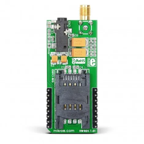
The Micro SIM card holder on the back of the Click board™ is used to install a micro SIM card. This device cannot be used without the valid SIM card, which allows connection to the cellular network. Both 1.8V and 3V SIM card types are supported.
Note: the antenna is sold separately.
Specifications
Type
2G GPRS,GSM/LTE
Applications
GSM Click™ with it’s Quectel M95 FA GSM/GPRS module is ideal for mobile devices
On-board modules
Quectel M95 FA GSM/GPRS
Key Features
GENERAL: Quad-band 850, 900, 1800, 1900MHz. DATA: supports PPP/ TCP/ UDP/ HTTP/ FTP/ SMTP/ SSL protocol stacks with Max. 85.6kbps (uplink & downlink).
Interface
GPIO,UART
Compatibility
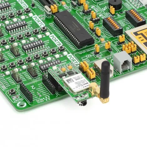
mikroBUS
Click board size
L (57.15 x 25.4 mm)
Input Voltage
3.3V or 5V
Pinout diagram
This table shows how the pinout on GSM2 click corresponds to the pinout on the mikroBUS™ socket (the latter shown in the two middle columns).
| Notes | Pin | Pin | Notes | ||||
|---|---|---|---|---|---|---|---|
| Indicates the module's operating status | STAT | 1 | AN | PWM | 16 | RI | Ring indication |
| Power on/off key | PWRKEY | 2 | RST | INT | 15 | CTS | Clear to send |
| Request to send | RTS | 3 | CS | RX | 14 | TXD | Transmit data |
| NC | 4 | SCK | TX | 13 | RXD | Receive data | |
| NC | 5 | MISO | SCL | 12 | NC | ||
| NC | 6 | MOSI | SDA | 11 | NC | ||
| Power Supply | 3V3 | 7 | 3.3V | 5V | 10 | 5V | Power Supply |
| Ground | GND | 8 | GND | GND | 9 | GND | Ground |
Onboard settings and indicators
| Label | Name | Default | Description |
|---|---|---|---|
| JP1 | I/O LEVEL | Left | Logic level voltage selection: left position 3.3V right position 5V |
| LD1 | PWR | - | Power indication LED |
| STAT | STAT | - | Device status indicator |
| NET | NET | - |
Software support
We provide a library for GSM2 click on our , as well as a demo application (example), developed using MikroElektronika and . The provided click library is mikroSDK standard compliant. The demo application can run on all the main MikroElektronika .
Library Description
The library carries a generic command parser adopted for AT command based modules. Generic parser.
Key functions:
gsm2_cmdSingle - Sends a provided command to the module.
gsm2_setHandler - Handler assignation to the provided command.gsm2_modulePower - Turns on the module.
Examples Description
The example demo application waits for the cal, and after the call is received the parser will get hang up.
This code snippet shows how a generic parser should be properly initialized. Before the initialization, the module must be turned on, and in addition to this, the hardware flow control should also be turned on.
Commands:
- The first command negotiates the baud rate with the module.
- The second command turns the echo off.
- The third command enables hardware flow control - necessary in case of UART polling.
- The fourth command sets up default message format.
void applicationInit()
{
// MODULE POWER ON
 gsm2_hfcEnable( true );
 gsm2_modulePower( true );

// MODULE INIT
 gsm2_cmdSingle( "AT" );
 gsm2_cmdSingle( "ATE0" );
 gsm2_cmdSingle( "AT IFC=2,2" );
 gsm2_cmdSingle( "AT CMGF=1" );
}
Along with the demo application, timer initialization functions are provided. Note that the timer is configured according to the default development system and MCUs, changing the system or MCU may require an update of timer init and timer ISR functions.
The full application code, and ready to use projects can be found on our .
Other mikroE Libraries used in the example:
- String
- Conversion
Additional notes and information
Depending on the development board you are using, you may need , or to connect to your PC, for development systems with no UART to USB interface available on the board. The terminal available in all MikroElektronika , or any other terminal application of your choice, can be used to read the message.
mikroSDK
This Click board™ is supported with - MikroElektronika Software Development Kit. To ensure proper operation of mikroSDK compliant Click board™ demo applications, mikroSDK should be downloaded from the and installed for the compiler you are using.
For more information about mikroSDK, visit the .


)")

